A New Chaotic Jerk Circuit
Much recent interest has been given to simple chaotic
oscillators based on jerk equations that involve a third-time
derivative of a single scalar variable. The simplest such
equation has yet to be electronically implemented. This paper
describes a particularly elegant circuit whose operation is
accurately described by a simple variant of that equation in
which the requisite nonlinearity is provided by a single diode
and for which the analysis is particularly straightforward.
(Manuscript received September 20, 2010; revised December 1, 2010;
accepted January 26, 2011. Date of current version April 20,
2011.)
Ref:
J.
C. Sprott, IEEE Transactions on Circuits and Systems--II:
Express Briefs
58,
240-243 (2011)
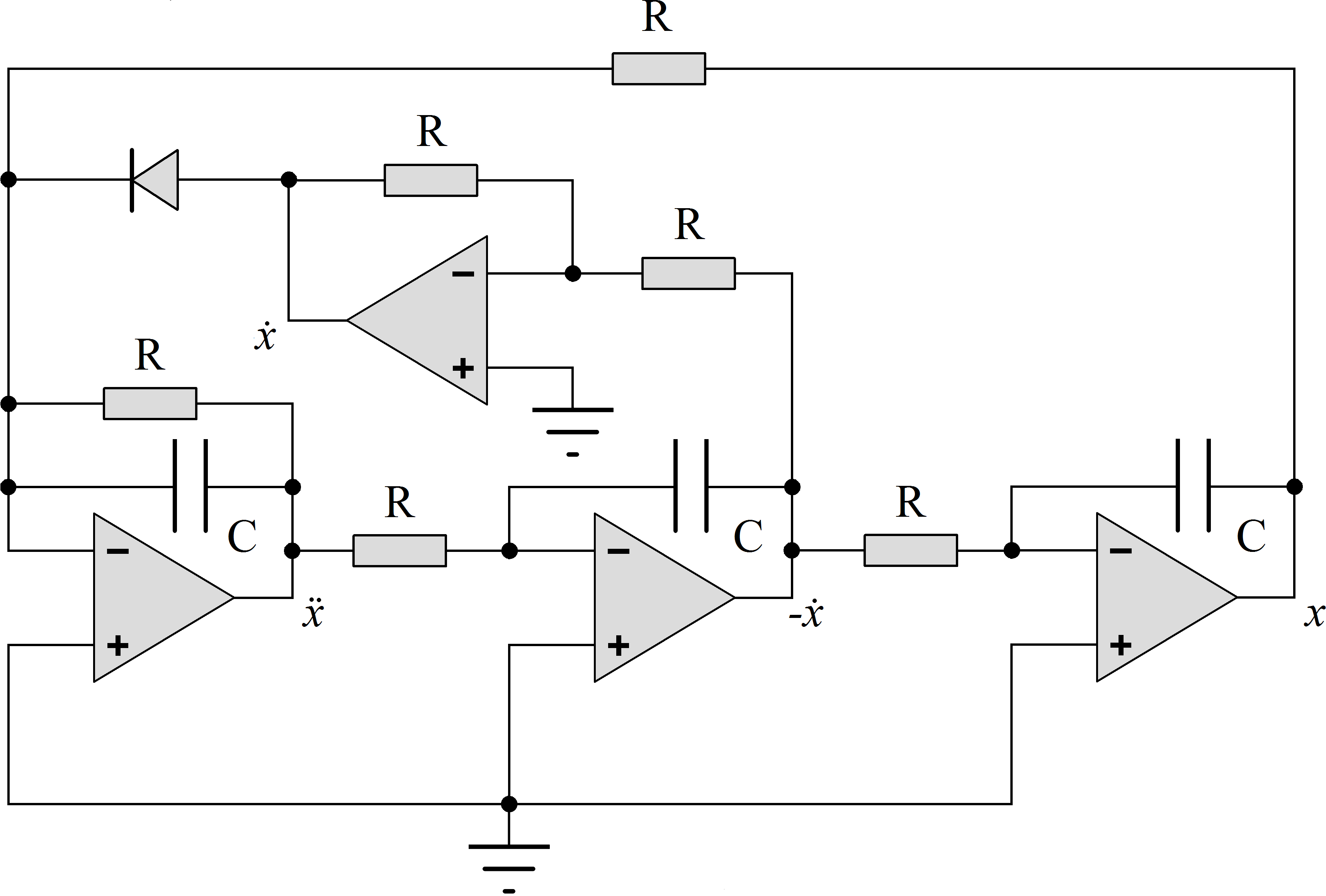
Fig. 1. Chaotic
circuit schematic.
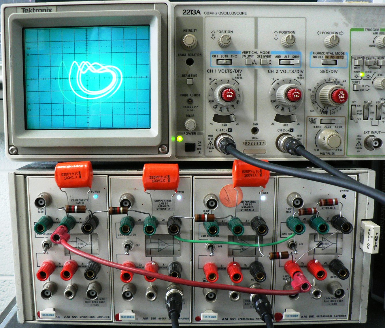
Fig. 2. Actual circuit in operation.
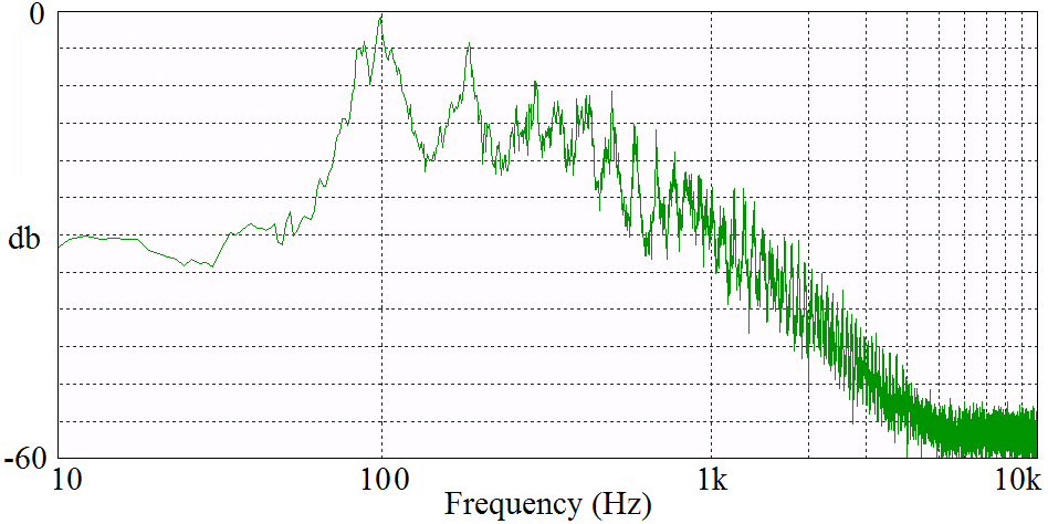
Fig. 3. Frequency spectrum of the
x output of the chaotic
circuit.
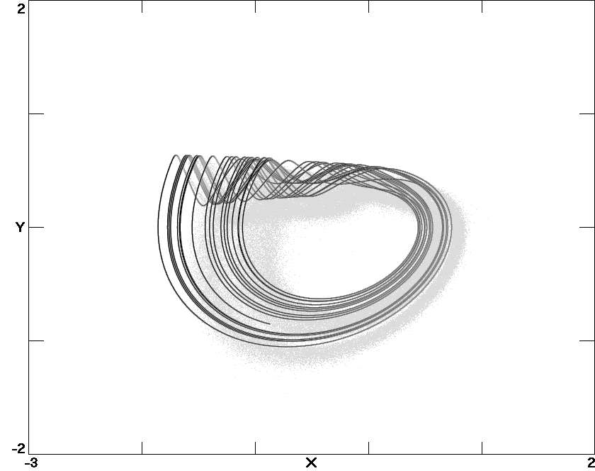
Fig. 4. Numerically calculated phase space plot on the same scale
as Fig. 2.
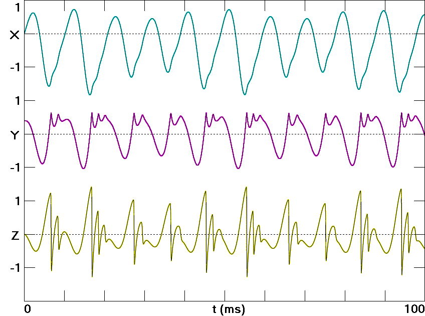
Fig. 5. Numerically calculated waveforms of
x and its
successive derivatives.
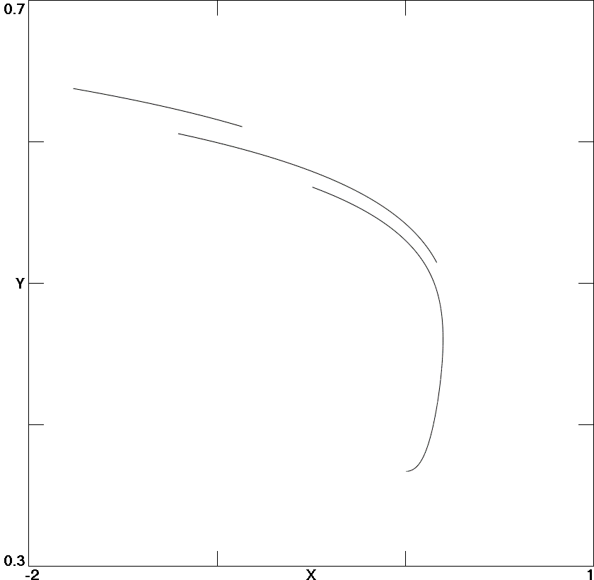
Fig. 6. Poincaré section in the x-y plane at the instant of
maximum diode conduction.
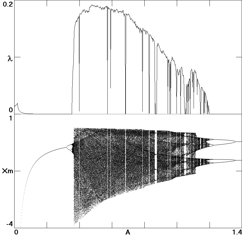
Fig. 7. Largest Lyapunov exponent and the value of
x when
dx/dt is a local maximum versus the bifurcation parameter
A
in (6).
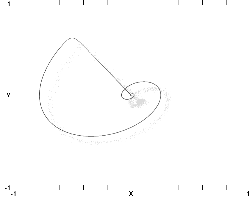
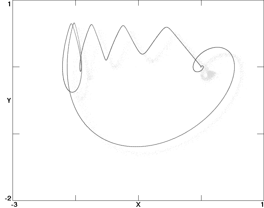
Fig. 8. Homoclinic orbits, with the upper for
A = 0.7043
and the lower for
A = 0.3890 in (6).